Info
This article was also posted in French on my club's website F6KOP
The objective of a choke balun is to reduce RF current flowing on the outside of the coaxial cable, thereby improving the symmetry of the radiation pattern and suppressing radio-frequency interference (RFI).
The target values for a choke balun vary from a few hundred Ω to several kΩ. Below 500 Ω, the effects are generally marginal, but common-mode current can remain significant. The 500–1000 Ω range is the lowest useful range for HF applications. Between 1 and 2 kΩ, a choke balun performs well. From 2 kΩ to 5 kΩ, performance is excellent, but achieving it over a wide frequency range, especially at high power, is difficult.

Choking impedance is often used to characterize a choke balun, but in practice it is usually calculated from the measured attenuation. During construction and testing, measuring attenuation with a VNA is both simpler and more precise than directly determining impedance. Therefore, throughout the rest of this article, choke performance will be discussed in terms of attenuation in dB.
The following formula is usually used to calculate the impedance from the attenuation:
| Attenuation | Calculation | Impedance |
|---|---|---|
|
$$ 20 dB $$
|
$$ 50 \times 10^1 $$
|
$$ 500 Ω $$
|
|
$$ 25 dB $$
|
$$ 50 \times 10^\frac{1}{25} $$
|
$$ 890 Ω $$
|
|
$$ 30 dB $$
|
$$ 50 \times 10^\frac{1}{5} $$
|
$$ 1580 Ω $$
|
|
$$ 35 dB $$
|
$$ 50 \times 10^\frac{1}{75} $$
|
$$ 2800 Ω $$
|
|
$$ 40 dB $$
|
$$ 50 \times 10^\frac{1}{75} $$
|
$$ 5000 Ω $$
|
A commonly cited design goal for choke baluns is to achieve at least 25 dB of common-mode attenuation across all relevant bands. To provide additional margin, our objective is to design a choke balun achieving a minimum attenuation of 30 dB.
Even if a choke balun appears to perform well, for example with a measured attenuation of 40 dB on a VNA, it may still overheat if losses in the ferrite are too high. Under high RF power, these losses convert part of the common-mode energy into heat. As the ferrite temperature rises, its magnetic properties change: the impedance can decrease while the resistive losses increase, creating a positive feedback loop. The additional heat further raises the temperature and can eventually lead to failure of the choke balun. This is the phenomenon that caused the failure of the choke balun used with our club 40-meter antenna.
Therefore, a high measured attenuation value at low power does not necessarily guarantee adequate power-handling capability. Attenuation and power rating are separate parameters. A choke can be electrically excellent but thermally inadequate.
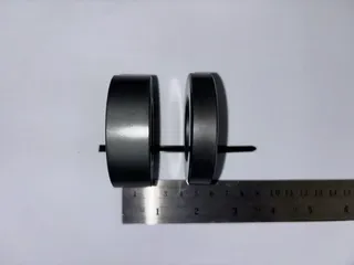
For this application, we are targeting a minimum attenuation of 30 dB. To minimize ferrite losses and reduce the risk of core overheating, we have increased the ferrite cross-section by using two type 31 ferrite cores per choke balun, each 20 mm thick. The number of turns has been optimized to achieve the required attenuation while keeping losses under control.
In addition, we are using a 2.6 mm PTFE-insulated coaxial cable specifically designed for high-power applications and capable of withstanding elevated temperatures, such as RG-400 or RG-142. While the coaxial cable must withstand the RF power, the ferrite core remains the critical component when evaluating the thermal limits of a choke balun.
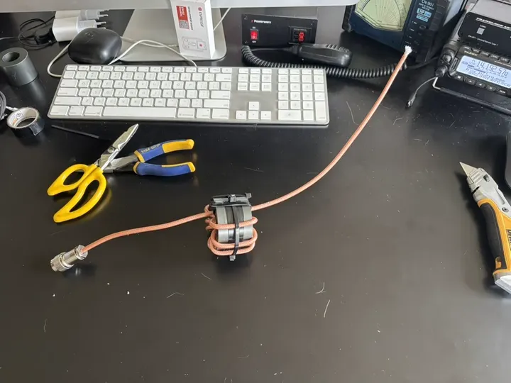
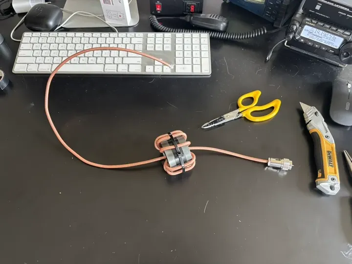
The images below show the choke balun we constructed. Two graphs present the measurements performed on the two choke baluns. On the 15 m and 20 m bands, both exhibit approximately 32 dB of attenuation. Finally, in the photo above, you can also see the difference in thickness between the ferrite cores we used and the ferrite commonly found from radio equipment suppliers.