Introduction
VHF and UHF1 bands form an essential part of the radio spectrum, supporting everything from amateur radio communications to public safety networks. These frequencies offer reliable local coverage and occasional opportunities for impressive distance work when conditions are favorable. The right antenna can make a dramatic difference in your station's performance, whether you're a beginner just getting started or an experienced operator looking to push the boundaries of what's possible on these bands.
Understanding the Basics
Before diving into specific antenna designs, it's worth understanding how wavelength directly influences antenna size and performance. At VHF/UHF frequencies, antennas are conveniently sized for home construction, making them perfect DIY projects. Factors like gain2, polarization3, and height above ground all play crucial roles in determining how far your signal will travel. Unlike HF communications, VHF and UHF signals generally travel by line-of-sight, making antenna height particularly important for extending your communication range.
Environmental Considerations for VHF/UHF Antennas
When planning for your VHF/UHF antenna installation, understand that these frequencies are significantly affected by terrain and obstacles. Unlike HF signals that can bounce off the ionosphere, VHF/UHF propagation is primarily line-of-sight with some diffraction and reflection. Hills, buildings, dense foliage, and even weather conditions can dramatically impact your signal:
- Elevated locations provide dramatically better performance. A modest antenna on a hilltop will outperform an excellent antenna in a valley.
- Metal structures cause significant signal blockage and multipath interference.
- Concrete buildings with steel reinforcement or stucco can attenuate signals by 20-30 dB.
- Dense foliage can absorb VHF/UHF signals, especially when wet. A 100-foot dense, damp forest section can reduce signal strength by 10dB or more at 440MHz.
- Rain, snow, and fog have minimal effects at lower VHF but become increasingly significant at upper UHF/SHF frequencies.
Easy DIY Antenna Projects
Quarter-Wave Ground Plane

The quarter-wave ground plane antenna is the simplest effective VHF/UHF operation antenna. It consists of a vertical radiating element that is one-quarter wavelength long, complemented by several ground radials extending outward. This design offers omnidirectional coverage, making it excellent for general-purpose communications where you need to hear and be heard in all directions. Its simple construction requires stiff wires, a SO-239 connector, and basic soldering skills. While it won't win any contests for extreme distance work, it provides reliable local and medium-range communications with minimal investment in time and materials.
J-Pole Antenna
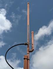
The J-Pole antenna resembles the letter "J" and offers several advantages over the ground plane design. The J-Pole antenna can be constructed from a copper pipe or ladder line and doesn't require ground radials. Making it easier to mount in confined spaces. It offers slightly better gain than a quarter-wave ground plane and presents a good match to 50-ohm coaxial cable without additional matching components. The J-Pole shines in fixed installations where omnidirectional coverage is needed, particularly for repeater access or local simplex nets. Its greater length slightly improves its performance compared to a quarter-wave antenna while remaining manageable for home construction and ordinary mounting situations. This antenna is often made from a ladder line or 300Ω tween lead, inserted into a Schedule-20 PVC4 pipe for permanent installation, or rolled up for portable operation.
Slim Jim Antenna
The Slim Jim builds upon the J-Pole concept with a folded design that resembles an elongated "J" with the top closed. This configuration provides broader bandwidth and slightly better performance than the standard J-Pole. Typically made from ladder lines for portable applications or copper pipes for permanent installations, the Slim Jim offers excellent omnidirectional coverage with minimal complexity. The antenna excels in portable operations, as it can be rolled up (in ladder line form) and easily deployed from trees or temporary supports. Its feed point location makes it less susceptible to common-mode currents on the feedline, often resulting in quieter reception.
Mid-Level Antenna Projects
Yagi Antennas
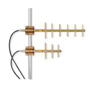
The Yagi antenna represents a significant step up in performance through directionality. Yagi designs focus signal energy in one direction using one driven element combined with reflectors and directors, significantly increasing the effective radiated power toward desired targets. A modest three-element Yagi can be simple to build while offering 7-9 dBi of forward gain. This directional characteristic makes Yagis excellent for point-to-point communications, working distant repeaters, or participating in VHF/UHF contests. The trade-off comes in aiming the antenna, often requiring a rotator for effective operation. Yagis offers an excellent introduction to directional antennas with a reasonable compromise between size, complexity, and performance gain.
Whether using FM for repeaters or SSB for DX, the antenna should be installed for vertical or horizontal polarization. Using the wrong polarization can result in 20dB or more signal attenuation.
Quad Antennas
Quad antennas employ full-wavelength loops rather than straight elements. This design offers several advantages, including better performance at lower heights and less susceptibility to noise. A two-element quad provides a similar gain to a three-element Yagi while often demonstrating a better front-to-back ratio (rejection of signals from behind). Despite these benefits, quad construction proves more challenging due to maintaining proper loop shapes and spacing. When properly built, however, quads deliver excellent directional performance, particularly for operators working in environments with significant local noise sources or those needing to reject signals from specific directions.
Coaxial Collinear Arrays
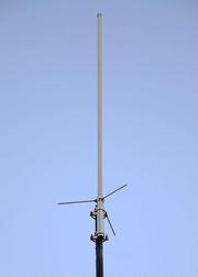
Collinear arrays stack multiple radiating elements vertically to increase gain while maintaining omnidirectional coverage. The collinear antenna is made of several sections of coaxial cable of precise lengths. These antennas concentrate energy toward the horizon rather than skyward, significantly extending the coverage. This design proves particularly valuable for fixed stations that need enhanced omnidirectional range without the complexity of rotatable directional systems. The construction requires precise measurements and careful attention to phasing details, but the result offers substantial improvement over simpler omnidirectional designs while still providing 360-degree coverage.
Advanced VHF/UHF Antennas for DX Work
High-Gain Yagi Arrays
For serious DX work, high-gain Yagi arrays represent the gold standard in terrestrial VHF/UHF communications. These antennas expand on basic Yagi principles by increasing element count (often to 10+ elements) and frequently stacking multiple Yagis vertically or horizontally to create arrays with extraordinary gain figures. Such systems can achieve forward gains exceeding 20 dBi, multiplying your receive and transmit apparent power by 100 times or more in the favored direction. These sophisticated antenna systems require careful attention to feed systems, matching networks, and mechanical stability. Their significant size and wind loading necessitate robust mounting systems. However, the performance rewards serious DX enthusiasts with the ability to work stations hundreds of miles away during enhanced propagation conditions.
Helical Antennas
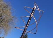
The helical antenna consists of a conducting wire wound in a helix shape, producing circular polarization that proves ideal for satellite communications. This polarization helps overcome signal fading caused by Faraday rotation as signals pass through the ionosphere. Helical designs offer moderate to high gain with reasonably compact dimensions compared to other high-gain systems. The construction requires maintaining precise spacing and turn dimensions, presenting building challenges. Despite its specialized construction requirements for amateur satellite operators or those interested in working orbiting repeaters, the helical antenna's circular polarization and predictable pattern make it an excellent choice.
EME (Earth-Moon-Earth) Antenna Systems

The ultimate DX challenge in VHF/UHF operation involves bouncing signals off the moon's surface to reach stations on the opposite side of the Earth. This demanding application requires extremely high-gain antenna systems, often featuring massive Yagi arrays or parabolic dishes. These systems must include low-noise preamplifiers mounted at the antenna and sophisticated elevation-azimuth rotator systems to track the moon's position. While representing the most complex and expensive antenna option, EME systems enable extraordinary communications, allowing contacts spanning thousands of miles on bands limited to line-of-sight distances. For those willing to invest the resources, EME operation represents the pinnacle of VHF/UHF technical achievement.
Practical Tips for Installation
Proper installation dramatically affects antenna performance, particularly at VHF/UHF frequencies. Height above ground proves especially critical, as each doubling of height potentially increases the range by 40%. Choosing the right feedline minimizes signal loss, which is crucial on UHF, where cheap coax can waste most of your signal.
Lightning protection isn't just about safety; it preserves your investment and station equipment. For directional antennas, rotator systems must be sized appropriately for the antenna's weight and wind loading. Attention to these installation details often makes more of a difference than choosing a marginally better antenna design.
Testing and Optimization
Even well-designed antennas benefit from thorough testing and optimization to ensure they operate efficiently in real-world conditions.

- SWR Meter: The most common tool for antenna testing is the SWR (Standing Wave Ratio) meter. It measures how much transmitted power is reflected back, indicating how well the antenna matches the transmission line and transceiver. For VHF and UHF, even small mismatches can cause significant power loss. An ideal SWR is 1:1, while values below 2:1 are considered good. Higher readings indicate issues such as incorrect element lengths or impedance mismatches.
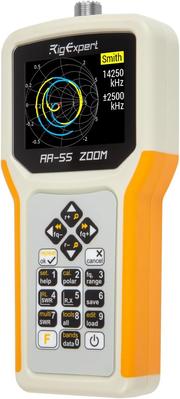
Antenna Analyzer - Antenna Analyzer: A VHF/UHF antenna analyzer provides real-time data on impedance, reactance, resonant frequency, and bandwidth for a more detailed assessment. Many modern analyzers can graph these characteristics across different frequencies, making tuning antennas like J-Poles, Slim Jims, or Yagis easier. Popular models like the NanoVNA offer wide-band analysis and data logging at an affordable price.
- Field Strength Meters and Signal Reports: Field strength meters help test your antenna's radiation pattern and confirm the direction and strength of the signal. This testing is crucial for directional antennas. Collaborating with another operator for on-air signal reports can provide valuable feedback on transmission and reception during live sessions.
- Modeling Software: Antenna modeling software, such as 4NEC2, MMANA-GAL, or EZNEC, allows you to simulate designs before construction, saving time and effort. These tools help you test variations in element length, spacing, and height, making it easier to identify performance issues.
- Final Adjustments: Small changes during testing can lead to significant improvements. Adjusting lengths, repositioning components, and enhancing grounding can help optimize performance. Be sure to test antennas in their final installed position, as factors like height and surroundings can impact their operation.
Conclusion
The journey from simple quarter-wave antennas to sophisticated DX arrays mirrors the progression many radio enthusiasts follow in their hobby. Each type of antenna offers a balance of performance, complexity, and resource requirements. Your best choice will depend on your specific communication goals, available space, and how much time and resources you're willing to invest. Regardless of your design, building your own antennas can lead to cost savings, a deeper understanding of radio fundamentals, and immense satisfaction when you hear those first distant signals coming through on equipment you crafted yourself.